foxd27 technical documentation Buy
Getting started with Fox board D27
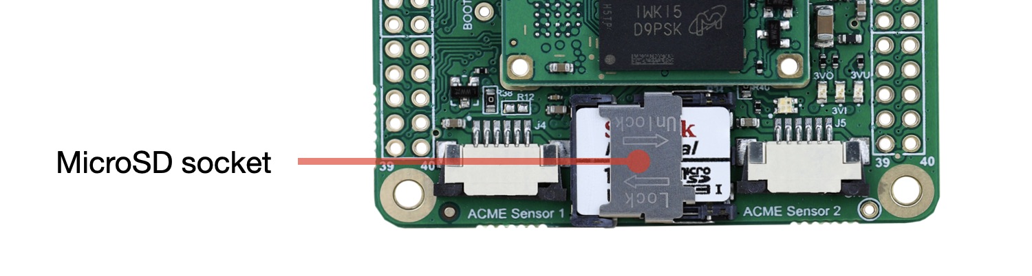
Fox Board D27 needs a bootable class='acmetable' microSD with Linux installed to start. You can buy a ready-to-use micorSD from this link on our website or a blank microSD and follow this article to save Linux on it.
Don't use very cheap microSD to do that. We suggest to use fast microSD for industrial use to avoid surprices during the use.
When ready insert the microSD inside the microsd socket:
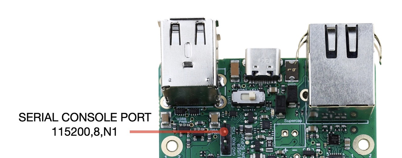
Check the messages generated during the boot using the serial console port. Any commercial USB/serial adapter at 3.3 volt can be used. On this site is available this product: USB to debug port adapter.
Configure your terminal emulator at 115200,N,8,1.
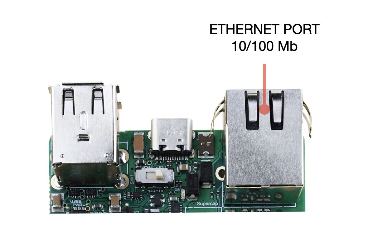
Wire the board to your LAN using the Ethernep port, the FOX Board D27 will get its IP address from your DHCP server.
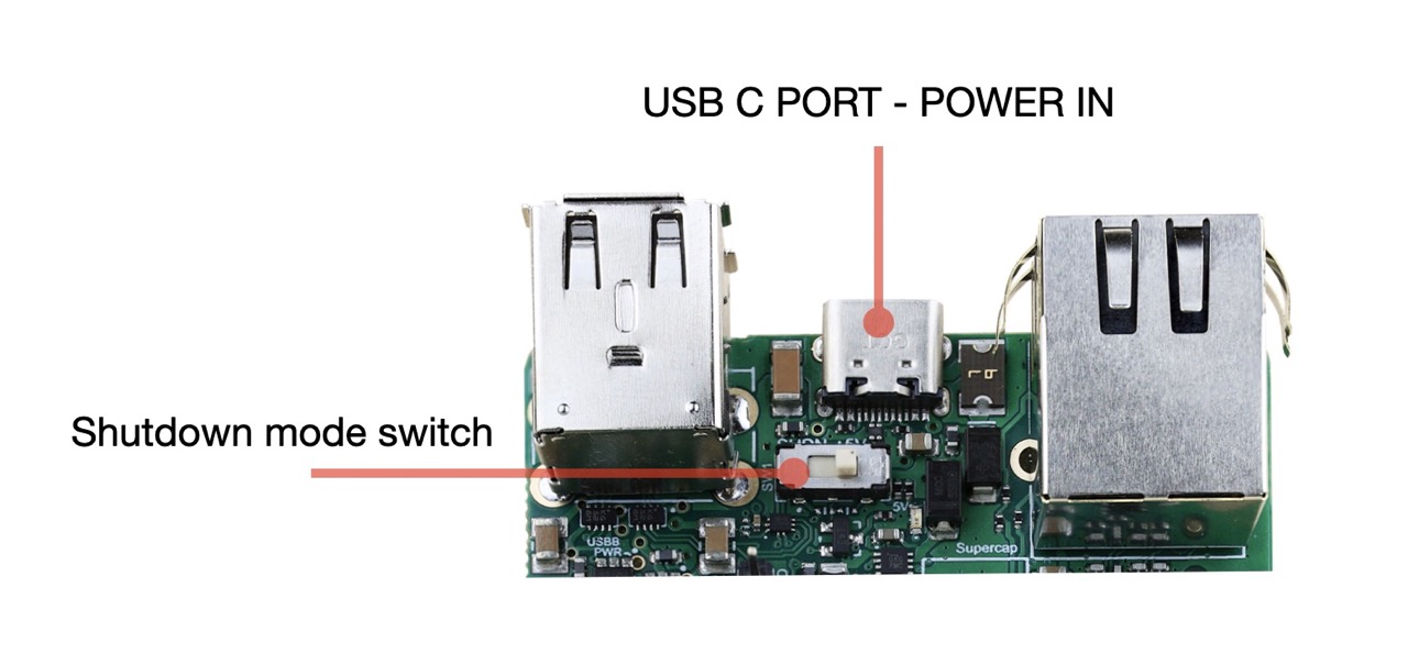
Provide the power to the board using an USB-C power supply. Check that the SHUTDOWN switch is turned on +5v position as shown on this photo.
Please note that this is not a power switch but is a switch used to enable the board to work in some low power modes.
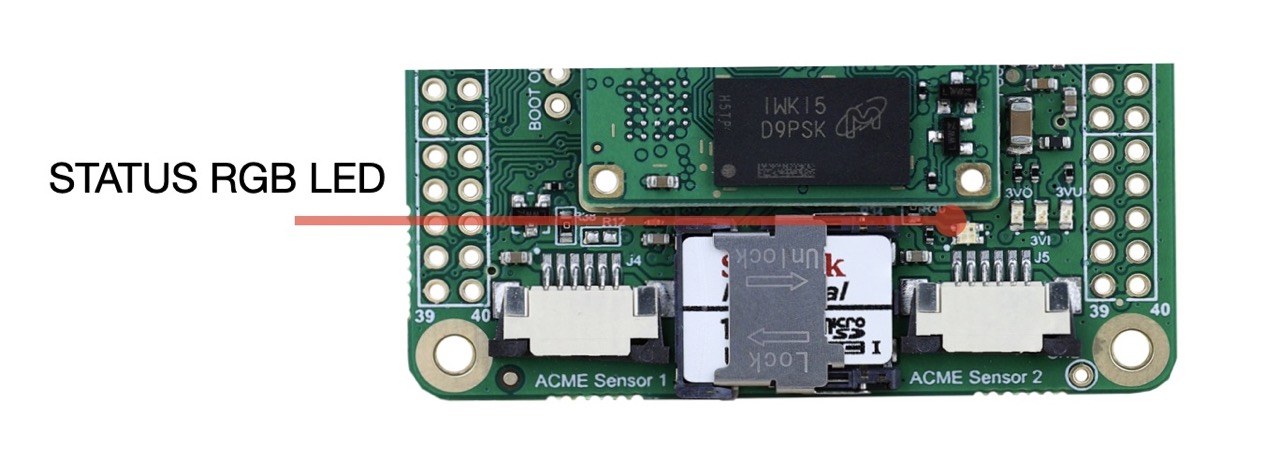
During the bootstrap a small RGB led will blink in this way:
- Red blinks indicates activities on microSD
- Green blinks indicates the CPU load
Get the access from the console port:
During the boot a lot of messages are sent over the serial port by the Linux Kernel. After a while a login message will appear:
foxd27 login: acme
Password: acmesystems
The command line prompt will appear waiting for your linux commands:
acme@foxd27:
Check for example your ip address by typing:
acme@foxd27: sudo ifconfig

eth0: flags=4163<UP,BROADCAST,RUNNING,MULTICAST>  mtu 1500
    inet 192.168.10.83  netmask 255.255.255.0  broadcast 192.168.10.255
    inet6 fe80::fec2:3dff:fe54:3f64  prefixlen 64  scopeid 0x20<link>
    ether fc:c2:3d:54:3f:64  txqueuelen 1000  (Ethernet)
    RX packets 2357  bytes 235274 (229.7 KiB)
    RX errors 0  dropped 0  overruns 0  frame 0
    TX packets 395  bytes 39181 (38.2 KiB)
    TX errors 0  dropped 0 overruns 0  carrier 0  collisions 0
    device interrupt 159  base 0x8000

lo: flags=73<UP,LOOPBACK,RUNNING>  mtu 65536
    inet 127.0.0.1  netmask 255.0.0.0
    inet6 ::1  prefixlen 128  scopeid 0x10<host>
    loop  txqueuelen 1000  (Local Loopback)
    RX packets 0  bytes 0 (0.0 B)
    RX errors 0  dropped 0  overruns 0  frame 0
    TX packets 0  bytes 0 (0.0 B)
    TX errors 0  dropped 0 overruns 0  carrier 0  collisions 0
In this case the IP is 192.168.10.83 and the MAC address is fc:c2:3d:54:3f:64.
This MAC address is world-wide unique for this board thanks to the Microchip AT24MAC402
mounted on the FOX D27. This chip contains also a unique 128-bit Serial Number and 2-kilobit of
serial EEPROM avalable for the user.
It is possible to know the IP address also using this command ip addr.
Using the USB port
Fox Board D27 has two USB 2.0 host ports. They are called USB-A and USB-B and are located as shown below:
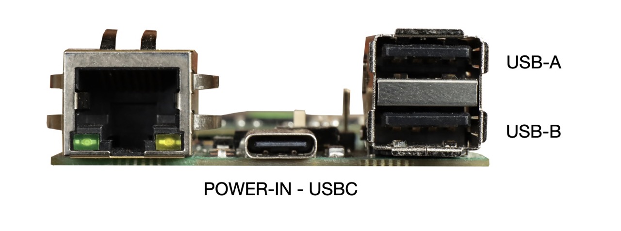
Each port can be turned-off by changing the logical state of some GPIO lines. By default both ports are on.
USB-A power line control (line PB25)
- ON
sudo gpioset gpiochip0 57=1 - OFF
sudo gpioset gpiochip0 57=0
USB-B power line control (line PB24)
- ON
sudo gpioset gpiochip0 56=1 - OFF
sudo gpioset gpiochip0 56=0
The port USB-A can work as host port ot client port. In this case the connector used is the USB-C power in connector.
Switch the USB-A line from the host connector to the device USBC connector (line PIOBU6)
- USB-A on host port
sudo gpioset gpiochip1 6=0 - USB-A on device port
sudo gpioset gpiochip1 6=1
To configure Linux to use the USB-A line as an USB client it is requested to change the Device Tree.
Manage the 3V3_USER power line
On J1 and J2 GPIO connectors there are two pins where is available a 3.3 volt power line interruptible by software usign the GPIO line PIOBU3. This line manages directly the ENABLE pin of PMIC that will provide the 3V3_USER powersupply.
- 3V3_USER ON
sudo gpioset gpiochip1 3=1 - 3V3_USER OFF
sudo gpioset gpiochip1 3=0
It is possible to check the state of this power out line by the green led 3VU
Manage the green leds used to display the power line states
Three green leds are used to display the state of some power lines inside the FOX Board D27
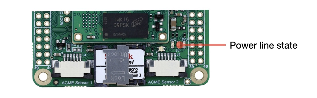
- 3VO - State of the 3.3 volt out from the Roadrunner SOM
- 3VI - State of the 3.3 volt input line to the Roadrunner SOM
- 3VU - State of the J1.1 and J2.1 3.3 volt user power out line
to limit the current absorption is it possible to turn-off this leds using this command (line PA26):
- ALL LEDS ON
sudo gpioset gpiochip0 26=1 - ALL LEDS OFF
sudo gpioset gpiochip0 26=0
Manage the RGB status led
The RGB status led uses three GPIO lines:
- PC9 red led
- PA25 green led
- PB13 blue led
by default this three lines is managed by the GPIO LED drived provided by Linux and activated inside the device tree by these lines:
leds {
        compatible = "gpio-leds";
        pinctrl-names = "default";
        pinctrl-0 = <&pinctrl_led_gpio_default>;
        status = "okay";

        red {
            label = "red";
            gpios = <&pioA PIN_PC9 GPIO_ACTIVE_LOW>;
            linux,default-trigger = "mmc0";
        };

        green {
            label = "green";
            gpios = <&pioA PIN_PA25 GPIO_ACTIVE_LOW>;
            linux,default-trigger = "heartbeat";
        };


        blue {
            label = "blue";
            gpios = <&pioA PIN_PB13 GPIO_ACTIVE_LOW>;
            linux,default-trigger = "none";
        };
    };
It is possible to change the default trigger (in other words the way to use these leds) changing the device three or using the filesystem three available on /sys/class/leds.
ls /sys/class/leds

blue  green  mmc0::  red
Examples:
Turn on the blue led:
sudo sh -c "echo '1' >> /sys/class/leds/blue/brightness"
Turn off the blue led:
sudo sh -c "echo '0' >> /sys/class/leds/blue/brightness"
Disable the trigger for the red amd green led:
sudo sh -c "echo 'none' >> /sys/class/leds/red/trigger"
sudo sh -c "echo 'none' >> /sys/class/leds/green/trigger"
Turn off the green and red leds:
sudo sh -c "echo '0' >> /sys/class/leds/green/brightness"
sudo sh -c "echo '0' >> /sys/class/leds/red/brightness"
Read the trigger enable for the red led
cat /sys/class/leds/red/trigger

[none] rfkill-any rfkill-none kbd-scrolllock kbd-numlock kbd-capslock kbd-kanalock kbd-shiftlock kbd-altgrlock kbd-ctrllock kbd-altlock kbd-shiftllock kbd-shiftrlock kbd-ctrlllock kbd-ctrlrlock timer heartbeat gpio cpu cpu0 mmc0
Removing the device tree association with the gpio-leds Linux driver inside the device tree might be possible to control the status led using directly these commands:
- RED ON (PC9)
sudo gpioset gpiochip0 73=0 - RED OFF (PC9)
sudo gpioset gpiochip0 73=1 - GREEN ON (PA25)
sudo gpioset gpiochip0 25=0 - GREEN OFF (PA25)
sudo gpioset gpiochip0 25=1 - BLUE ON (PB13)
sudo gpioset gpiochip0 45=0 - BLUE OFF (PB13)
sudo gpioset gpiochip0 45=1
Related products
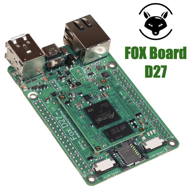
- Low power consumption
- Two USB Host 2.0 ports (one configurable as USB client on the USB-C connector)
- One 10/100 Mbit/s Lan port
- 2 Acme Sensor ports
- Huge set of GPIOS, SPI, I2C and serial lines
- CPU Microchip SAMA5D27
- Cortex A5 @ 500 MHz
- Low power consumption:
Suspend to RAM mode 10mW
Full speed: 396mW - Debian, Buildroot and Yocto Linux
- Fully open source drivers
- All the circuitries you need to test the RoadRunner SOM
- USB host, USB device, Ethernet port, MicroSD socket
- Test points for power consumption measurements
- All the Roadrunner signals exposed on 2.54mm pitch pins
- On-board supercap for RTC and backup memory circuit