CM Panel technical documentation Buy
USB to serial adapters - Static assignment of serial devices
This is the output of the lsusb command when I insert an USB-serial converter into each of the available USB ports:
$ lsusb

Bus 001 Device 028: ID 067b:2303 Prolific Technology, Inc. PL2303 Serial Port / Mobile Phone Data Cable
Bus 001 Device 030: ID 067b:2303 Prolific Technology, Inc. PL2303 Serial Port / Mobile Phone Data Cable
Bus 001 Device 029: ID 067b:2303 Prolific Technology, Inc. PL2303 Serial Port / Mobile Phone Data Cable
Bus 001 Device 003: ID 0424:ec00 Microchip Technology, Inc. (formerly SMSC) SMSC9512/9514 Fast Ethernet Adapter
Bus 001 Device 002: ID 0424:9514 Microchip Technology, Inc. (formerly SMSC) SMC9514 Hub
Bus 001 Device 001: ID 1d6b:0002 Linux Foundation 2.0 root hub
The first three lines are related to the detected usb-to-serial converters.
$ ls -al /dev/ttyUSB*

crw-rw-rw- 1 root dialout 188, 0 Mar  4 16:56 /dev/ttyUSB0
crw-rw-rw- 1 root dialout 188, 1 Mar  4 16:56 /dev/ttyUSB1
crw-rw-rw- 1 root dialout 188, 2 Mar  4 16:57 /dev/ttyUSB2
These are the devices created dynamically. The assignment between the logical device and the physical port depends exclusively on the sequence of insertion of the adapters.
To understand which logical device corresponds to which physical USB port, we give for example the following command:
$ udevadm info /dev/ttyUSB0 | grep "ID_PATH="

E: ID_PATH=platform-fe980000.usb-usb-0:1.4:1.0
This means that the device /dev/ttyUSB0 physically matches with USB port 4.
In this photo, it is possible to see the numbering of the USB ports of the CM-Panel POE:

To fix the assignment between physical USB port and logical serial device, these three lines can be inserted into the file /etc/udev/rules.d/99-usb-serial.rules.
$ sudo nano /etc/udev/rules.d/99-usb-serial.rules

ENV{ID_PATH}=="platform-fe980000.usb-usb-0:1.2:1.0", SUBSYSTEM=="tty", ATTRS{idVendor}=="067b", ATTRS{idProduct}=="2303", SYMLINK+="ttySerial1", GROUP="dialout", MODE="0666"
ENV{ID_PATH}=="platform-fe980000.usb-usb-0:1.3:1.0", SUBSYSTEM=="tty", ATTRS{idVendor}=="067b", ATTRS{idProduct}=="2303", SYMLINK+="ttySerial2", GROUP="dialout", MODE="0666"
ENV{ID_PATH}=="platform-fe980000.usb-usb-0:1.4:1.0", SUBSYSTEM=="tty", ATTRS{idVendor}=="067b", ATTRS{idProduct}=="2303", SYMLINK+="ttySerial3", GROUP="dialout", MODE="0666"
Disconnect the adapter and reconnect to the same port or type this command.
sudo udevadm control --reload-rules && sudo udevadm trigger
Then type:
$ watch -n 1 ls -al /dev/ttySerial1 /dev/ttySerial2 /dev/ttySerial3

lrwxrwxrwx 1 root root 7 Mar  4 17:36 /dev/ttySerial1 -> ttyUSB0
lrwxrwxrwx 1 root root 7 Mar  4 17:36 /dev/ttySerial2 -> ttyUSB1
lrwxrwxrwx 1 root root 7 Mar  4 17:37 /dev/ttySerial3 -> ttyUSB2
The assignment of the logical device to the physical port is now as follows, regardless of the insertion order_

Products related

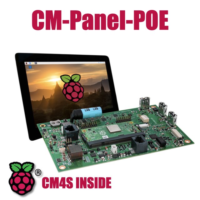
- 7 inch TFT display 800x480 pixel
- Capacitive touch
- Embedded micro UPS for safe shutdown
- Power Over Ethernet @ 10/100 Mbit
- Hi-resolution audio up to 384KHz@32bit
- Real Time Clock with backup battery
- 3 USB Host port
- 1 RS485/422/RS232 port
- 1 Relay
- MIPI Camera connector
- WiFi @ 2.4 GHz (optional)