CM Panel technical documentation Buy
Make a Raspberry Pi OS microSD for CM-Panel POE (Old CM3+ version)
This article explains how to create a standard Raspbian Pi OS MicroSD to use on the CM-Panel POE starting
from an official Raspberry Pi MicroSD image
Step-by-step guide
Download the image of standard Raspberry OS Version 2020-12-02 from these links:
- Lite version:
- Desktop version:
Flash a microSD SD using Balena Etcher software.
Mount the microSD just created on your PC (Linux or Windows) or your Mac. The first microSD partition labeled "boot" is formatted as FAT32 and visible on any system. These files are to edit using an ASCII editor:
Edit cmdline.txt
Change:
console=serial0,115200
in:
console=serial1,115200
Edit config.txt
Change the content of config.txt file in:
# For more options and information see
# http://rpf.io/configtxt
# Some settings may impact device functionality. See link above for details

# uncomment if you get no picture on HDMI for a default "safe" mode
#hdmi_safe=1

# uncomment this if your display has a black border of unused pixels visible
# and your display can output without overscan
#disable_overscan=1

# uncomment the following to adjust overscan. Use positive numbers if console
# goes off screen, and negative if there is too much border
#overscan_left=16
#overscan_right=16
#overscan_top=16
#overscan_bottom=16

# uncomment to force a console size. By default it will be display's size minus
# overscan.
#framebuffer_width=1280
#framebuffer_height=720

# uncomment if hdmi display is not detected and composite is being output
#hdmi_force_hotplug=1

# uncomment to force a specific HDMI mode (this will force VGA)
#hdmi_group=1
#hdmi_mode=1

# uncomment to force a HDMI mode rather than DVI. This can make audio work in
# DMT (computer monitor) modes
#hdmi_drive=2

# uncomment to increase signal to HDMI, if you have interference, blanking, or
# no display
#config_hdmi_boost=4

# uncomment for composite PAL
#sdtv_mode=2

#uncomment to overclock the arm. 700 MHz is the default.
#arm_freq=800

# Uncomment some or all of these to enable the optional hardware interfaces
dtparam=i2c_arm=on
#dtparam=i2s=on
#dtparam=spi=on

# Uncomment this to enable infrared communication.
#dtoverlay=gpio-ir,gpio_pin=17
#dtoverlay=gpio-ir-tx,gpio_pin=18

# Additional overlays and parameters are documented /boot/overlays/README

# Enable audio (loads snd_bcm2835)
#dtparam=audio=on

[pi4]
# Enable DRM VC4 V3D driver on top of the dispmanx display stack
#dtoverlay=vc4-fkms-v3d
#max_framebuffers=2

[all]
#dtoverlay=vc4-fkms-v3d

# -------------------------
# ACME Systems
# -------------------------
dtoverlay=goodix-7-acme
dtoverlay=disable-wifi
dtoverlay=disable-bt

#Ignore the HDMI cable hotplug (to avoid the delay at startup)
hdmi_ignore_hotplug=1

dtoverlay=pi3-disable-bt

# Debug port /dev/ttyS0
enable_uart=1
dtparam=uart1=on
dtoverlay=uart1,txd1_pin=32,rxd1_pin=33

# RS232/RS485/RS422 port on /dev/ttyAMA0
force_turbo=1
dtoverlay=uart0,txd0_pin=36,rxd0_pin=37,pin_func=6

# I2C 1 port on GPIO44 and GPIO45 to talk with the
# touch screen controller and camera crypto-chip
dtparam=i2c_arm=on
dtparam=i2c=on
dtparam=i2c_arm_baudrate=100000
dtoverlay=i2c1,pins_44_45
dtoverlay=i2c1-rtc,pcf8523

## Enable the DPI port to talk with the TFT display
dtoverlay=dpi18
overscan_left=0
overscan_right=0
overscan_top=0
overscan_bottom=0
framebuffer_width=800
framebuffer_height=480
enable_dpi_lcd=1
display_default_lcd=1
dpi_group=2
dpi_mode=87
dpi_output_format=0x6f005
hdmi_timings=800 0 40 48 88 480 0 13 3 32 0 0 0 60 0 32000000 6

start_x=1
gpu_mem=128

# Enable second I2C Bus 3
dtoverlay=i2c-gpio,bus=3,i2c_gpio_delay_us=1,i2c_gpio_sda=35,i2c_gpio_scl=27

# Set the pull up (input) pins 27 and 35
gpio=27,35=pu

dtparam=audio=off
dtoverlay=i2s-gpio28-31
dtoverlay=hifiberry-dacplus

# Rotate the LCD
#display_rotate=2
#framebuffer_width=800
#framebuffer_height=480
Download and save some binaries
In the first partition of the microSD save these binary files:
Root directory /
Directory /overlays
Insert the microSD inside the CM-Panel POE microSD socket
Remove the Supercap jumper
Close JUMP PROG BYPASS and power up the CM-Panel POE
Products related
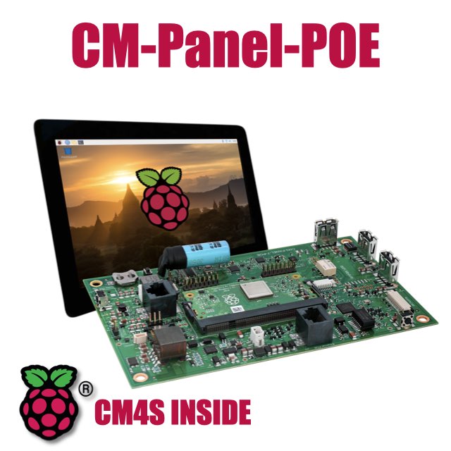
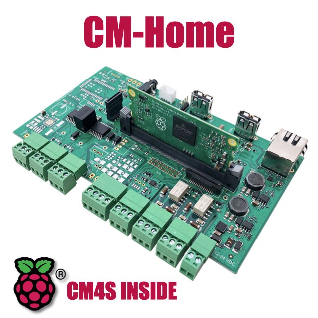
All-in-one 7 inch touch POE terminal powered by Raspberry Pi CM4S
- 7 inch TFT display 800x480 pixel
- Capacitive touch
- Embedded micro UPS for safe shutdown
- Power Over Ethernet @ 10/100 Mbit
- Hi-resolution audio up to 384KHz@32bit
- Real Time Clock with backup battery
- 3 USB Host port
- 1 RS485/422/RS232 port
- 1 Relay
- MIPI Camera connector
- WiFi @ 2.4 GHz (optional)